Pipestop-250 Linestop Machine and Equipment
Pipestop-250, linestop machines and associated equipment are lightweight and are designed to function easily on high-pressure lines, 4" - 12"; and on most types of pipelines and fluids. Maximum line pressure: 250 psi. Maximum Temperature: 350° F (121° C)
Product Image |
Product |
Item # |
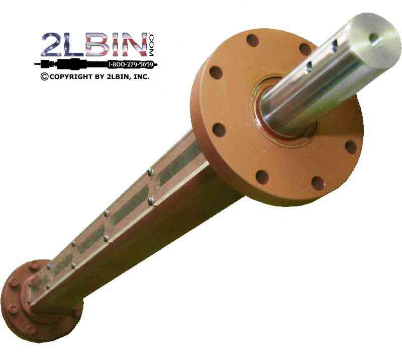  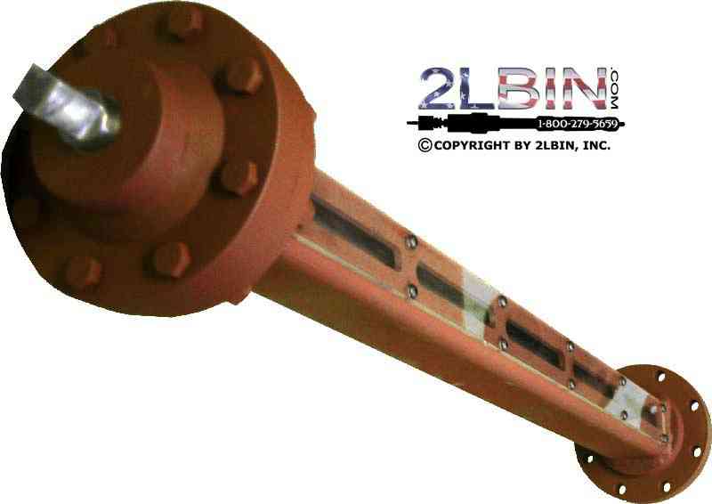 |
PSJ-0012-500 |
|
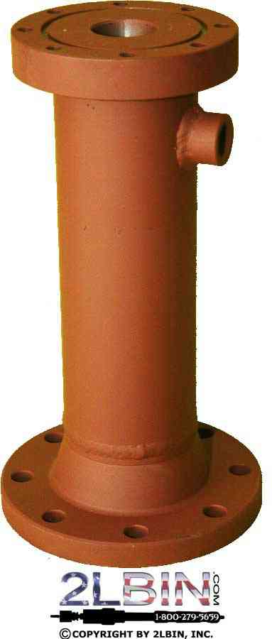 |
PSH-0004-275 |
|
6" Linestop Housing, ANSI 150 |
PSH-0006-275 |
|
10" Linestop Housing, ANSI 150 |
PSH-0010-275 |
|
    |
PSH-0004-275 |
|
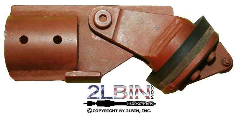
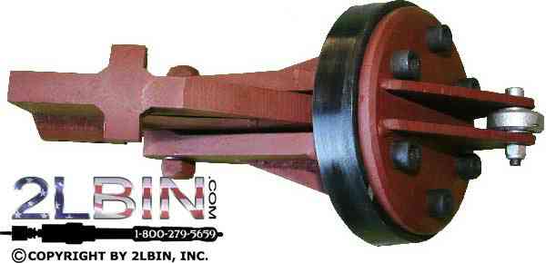
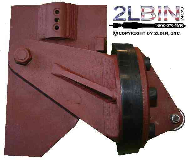
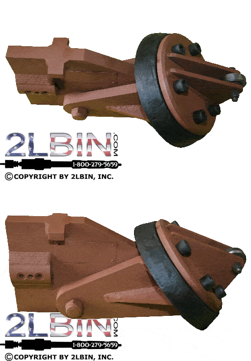
6" Pivoting Head for Line Stopping |
PSH-0006-275 |
|
8" Pivoting Head for Line Stopping |
PSH-0008-275 |
|
10" Pivoting Head for Line Stopping |
PSH-0010-275 |
|
12" Pivoting Head for Line Stopping |
PSH-0012-275 |
|
  More Information |
4" Linestop Cup |
BNLC-03875-0040 |
6" Linestop Cup |
BNLC-05875-0060 |
|
8" Linestop Cup |
BNLC-07875-0080 |
|
10" Linestop Cup |
BNLC-09875-0100 |
|
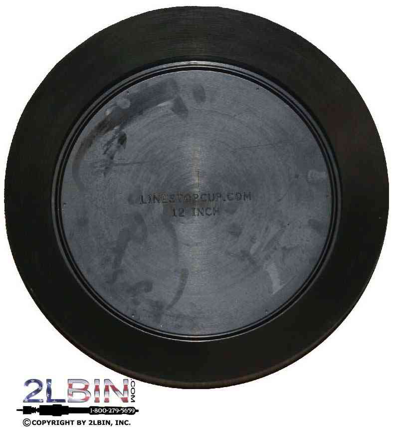
12" Linestop Cup |
BNLC-11875-0120 |
|
 |
||
 |
||
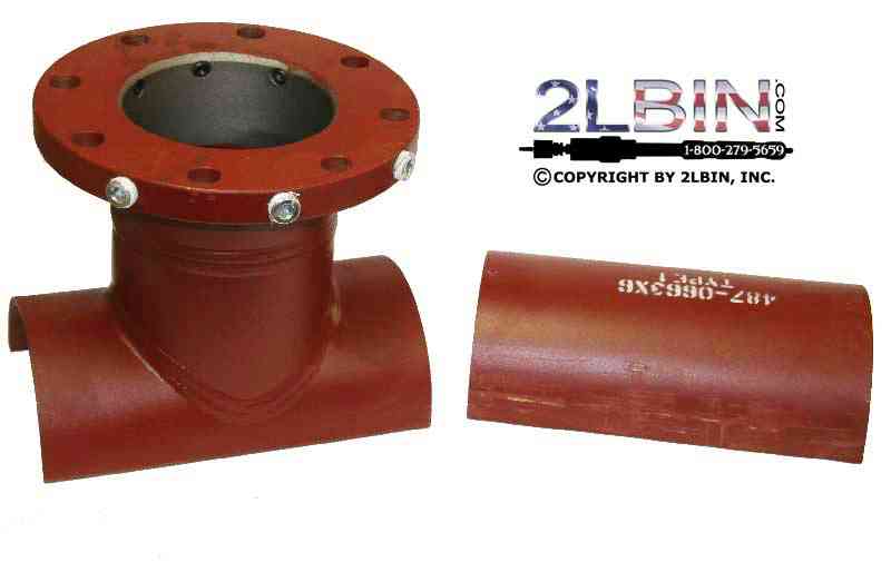 |
||
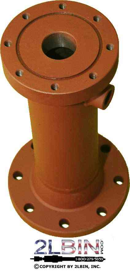 |
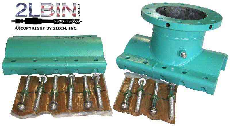
4" – 8" Housing, ANSI 150, ANSI 150 |
PSH-0008-275 |
10"-12" Housing, ANSI 150 |
PSH-0012-275 |
|
 |
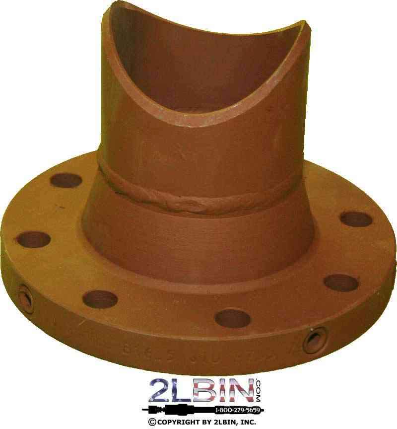
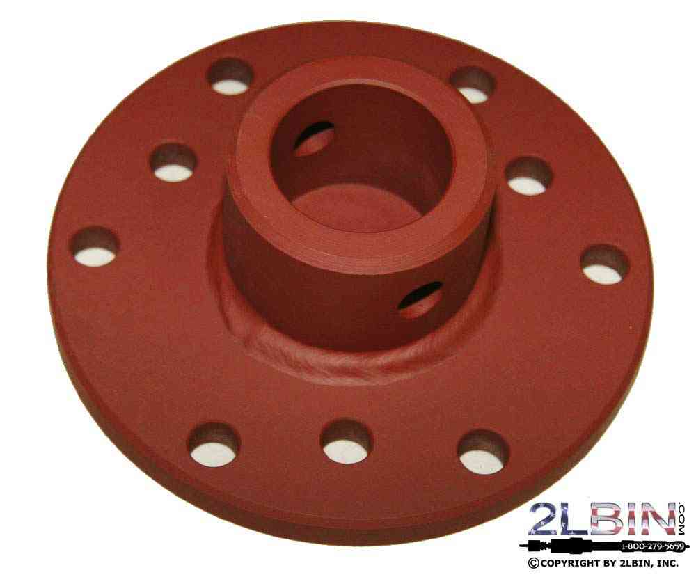
8" x 4" Flange Adapter, ANSI 150 |
DMF-0408-275 |
8" x 6" Flange Adapter, ANSI 150 |
DMF-0608-275 |
|
10" x 12" Flange Adapter, ANSI 150 |
DMF-1012-275 |
|
 More Information |
CPH-0408-275 |
|
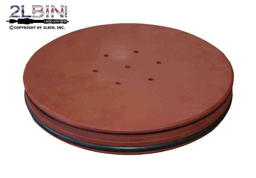
10"-12"Completion Plug Holder |
CPH-1012-275 |
|
 More Information |
4" Completion Plug, ANSI 150 |
|
6" Completion Plug, ANSI 150 |
||
8" Completion Plug, ANSI 150 |
||
10" Completion Plug, ANSI 150 |
||
12" Completion Plug, ANSI 150 |
||
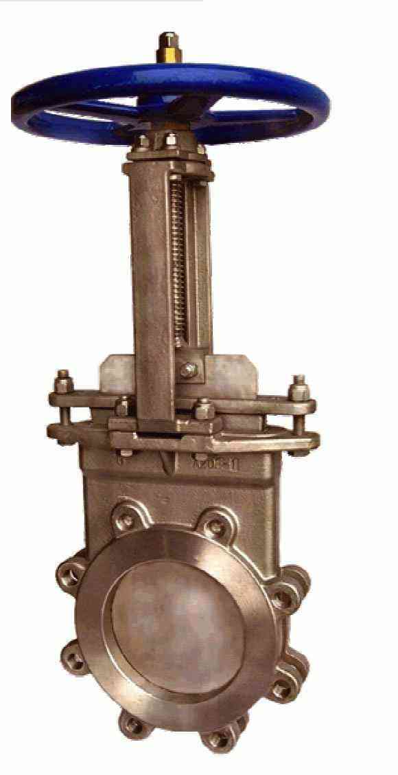
4" Knife Gate Valve, ANSI 150 |
ALV-0004-275 |
|
6" Knife Gate Valve, ANSI 150 |
||
8" Knife Gate Valve, ANSI 150 |
ALV-0006-275 |
|
10" Knife Gate Valve, ANSI 150 |
ALV-0010-275 |
|
| 12" Knife Gate Valve, ANSI 150 |
||
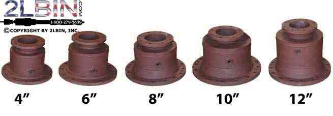 |
PSA-0004-275 |
|
6" Linestop Tapping Adapter, ANSI 150 |
PSA-0006-275 |
|
8" Linestop Tapping Adapter, ANSI 150 |
PSA-0008-275 |
|
10" Linestop Tapping Adapter, ANSI 150 |
PSA-0010-275 |
|
12" Linestop Tapping Adapter, ANSI 150 |
PSA-0012-275 |
|
 |
XL-Jackscrew for Line Stopping |
PSJ-XL12-500 |
| A Lesson in Line Stopping What is line stopping? Also called pressure plugging, line stopping is essentially the installation of a temporary valve in a line where one does not exist. Line stops are used to: - isolate or "dead-end" a pipeline; - relocate a pipeline with two permanent valves; - relocate a pipeline without permanent valves; - install a valve into a pipeline without a shutdown; - install a piece of process equipment into a pipeline without a shutdown; and, - Laterally install "non-tappable" valves. Since a line stop operation can be repeated at a later date, many pipe and gas companies install line stop fittings instead of valves at points where a valving action will inevitably be required. Types of line stops Four types of line stops or pressure plugs get the job done: Cylindrical plug A cylindrical plug made of elastomer or steel is used to stop the line by sealing against machined surfaces. Elastomer cup An elastomer cup seals against the pipe bore. This popular seal is affected by line pressure and is available in the greatest range of pressures and sizes. Expandable elastomer An expandable elastomer stopper seals against the bore of the pipe. This type is for low-pressure applications only. Inflatable gas bag An inflatable gas bag or balloon seals against the bore of the pipe. This seal is generally independent of line pressure and must be restricted to very low pressures. Technique When line stopping, determining the best method is extremely important. There is no universal line stopping technique and the right technique depends on the following variables: - temperature; - pressure; - size of main and wall thickness; - interior condition of main deposits, corrosion, weld beads, etc.; - duration of the line stop; - degree of leakage tolerated; and, - the flowing medium. Complete, "bubble tight", shutoff is difficult to achieve. When it is achieved, it is usually the result of good job site techniques. On hazardous jobs, like steam or flammables, the use of special flanges can maintain a safe environment. (Pipe O.D. - (2 x Pipe Wall) = I.D.) This simple formula can be the most important factor in reaching a "bubble tight" shutoff. The pipe I.D. must be verified for every line stop. Step-by-step A special line stop fitting is installed on the pipeline either by welding or using a mechanical seal. After pressure testing, a temporary valve is installed onto the fitting. First, a hole is made in the pipe with a special cutter. When the pressure tap is completed, the cutter and coupon are retracted into the tapping machine and the temporary valve is closed. If bypass taps are required, they are also made at this time. The tapping machine is removed from the temporary valve and replaced by a line stop machine. The valve is opened and the line stop plugging head is lowered in place, cutting off flow in the pipeline. To verify the effectiveness of the plugging head seal and to test the seal’s efficiency, a bleed-off point must be used. By opening the bleed-off and reducing the pressure on the downstream side of the head, or in the case of double line stops, in between stops, the pipeline pressure is used to help seal the plugging head. When the work is completed and the line stop must be removed, the line pressure is equalized on the "dead" side of the plugging head. This allows the head to be retracted and for the line to be put back into service. To complete the operation, the line stop machines are removed and completion machines are installed onto the temporary valves. A special closure plug is installed into the outlet flange of the line stop fitting, and the line stop machines and temporary valves are removed. Finally, a blind flange is usually installed to finish the line stop operation. |
||
Leave us a Facebook Comment

